November 1, 2026 · admin
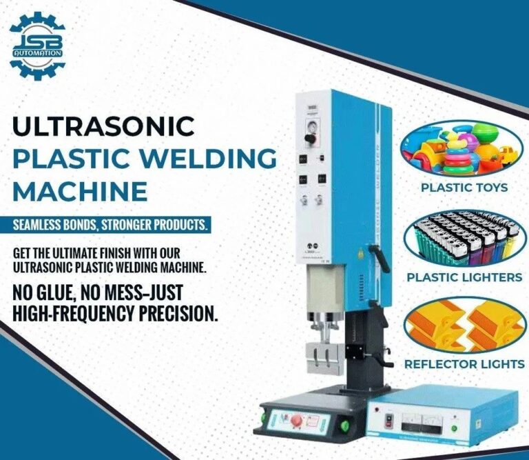
Manufacturers searching for an ultrasonic plastic welding machine manufacturer need more than a machine price or power rating. The right equipment must match the plastic material, component design, weld strength, production target, and quality requirements.
For businesses in Sonipat, including manufacturers in Kundli, Rai, Barhi, Murthal, and Kharkhoda, selecting a suitable ultrasonic plastic welding machine starts with understanding the application. A properly selected system can help produce consistent joints, reduce avoidable rejections, and support repeatable manufacturing.
In this guide, JSB Ultrasonic explains how to calculate machine requirements, compare power and frequency options, estimate production capacity, and prepare the right information before requesting a quotation.
Why Do Manufacturers in Sonipat Consider Ultrasonic Plastic Welding?
Ultrasonic plastic welding uses high-frequency mechanical vibration to generate heat at a suitable joint between compatible thermoplastic parts. The material softens at the joint and forms a bond under controlled process conditions.
Depending on the product and material, ultrasonic welding may be suitable for:
- Electrical and electronic plastic housings
- Automotive plastic components and interior parts
- Appliance covers and molded assemblies
- Consumer products and plastic enclosures
- Selected packaging and sealing applications
- Technical plastic components requiring repeatable assembly
Not every plastic or product design is suitable for ultrasonic welding. Material compatibility, joint design, and sample testing should be checked before final machine selection.
1. Identify the Plastic Material and Grade
The first step in ultrasonic welding machine selection is to identify the exact material used in both parts. Different thermoplastics have different stiffness, melting behavior, and welding characteristics.
| Plastic material | Example products | What to evaluate |
|---|---|---|
| ABS | Housings, covers, consumer products | Joint geometry, strength, and surface appearance |
| Polypropylene (PP) | Containers, appliance parts, molded components | Joint design and material-specific welding behavior |
| Polycarbonate (PC) | Transparent covers, lighting components | Cosmetic requirements and part protection |
| Polyamide (PA or nylon) | Engineering parts and technical assemblies | Material grade, moisture condition, and joint configuration |
| Polystyrene (PS) | Selected molded housings and consumer components | Joint dimensions and process settings |
When two different plastics are being joined, confirm that they can form a reliable bond. Similar-looking materials are not necessarily compatible for ultrasonic welding.
2. Measure Component Size and Weld Area
Component dimensions help determine the required horn, fixture, machine configuration, and welding arrangement. However, overall component size alone does not determine the required wattage.
For each part, record:
- Overall length, width, and height
- Wall thickness around the joint
- Weld path length or individual weld-point dimensions
- Joint type and geometry
- Required weld strength
- Appearance requirements and allowable witness marks
- Any leak-tightness or other product-specific test
For example, a compact electrical housing with a short joint may have different requirements from a large cover with a long continuous weld path. Material, joint design, energy transfer, tooling, and required cycle time all influence the final selection.
3. How to Calculate Ultrasonic Welding Machine Power
There is no universal formula that converts component dimensions or weld area directly into the exact required machine wattage. The power rating must be considered together with the material, joint design, horn, booster, amplitude, applied force, cycle time, and production duty.
The following categories can be used as preliminary discussion points when shortlisting a machine. They are not guaranteed specifications for any particular product.
| Application category | Preliminary power range to evaluate | Key validation point |
|---|---|---|
| Small precision components | Approximately 800–1200 W | Amplitude, joint quality, and cosmetic impact |
| General industrial plastic components | Approximately 1500–2000 W | Material, joint geometry, and cycle time |
| Larger or more demanding weld joints | Approximately 2600 W or higher | Tooling performance, energy distribution, and generator load |
Important: A larger machine is not automatically a better machine. The objective is to select a configuration that provides reliable weld quality without damaging the component or operating outside the intended process range.
Steps to validate the power requirement
- Identify the plastic material and joint design.
- Shortlist a suitable frequency and power category.
- Prepare a horn and fixture appropriate for the component.
- Run welding trials on representative parts.
- Inspect weld strength, appearance, deformation, and other quality requirements.
- Check generator loading and process repeatability under expected production conditions.
4. Choose the Correct Welding Frequency
Frequency affects the transducer, booster, and horn design. It also influences the tooling arrangement and the application range. The right frequency depends on the component, material, joint geometry, required amplitude, and production requirements.
| Frequency | General application context |
|---|---|
| 15 kHz | Many larger components and applications requiring substantial amplitude or robust tooling |
| 20 kHz | A wide range of general industrial plastic welding applications |
| 28–35 kHz | Selected smaller or more precision-sensitive components |
| 40 kHz | Selected small or delicate components requiring a suitable high-frequency setup |
These are general selection patterns, not strict rules. The machine generator, transducer, booster, and horn must be compatible with the selected frequency. Sample testing is recommended before finalizing the configuration.
5. Calculate the Production Capacity Required
Production planning is especially important when deciding between a standard machine, a dedicated welding station, and an automated configuration.
Ideal processing time = Daily production quantity × Cycle time per part
Consider an example for a manufacturer in Sonipat:
- Daily production target: 2,400 parts
- Validated cycle time: 4 seconds per part
- Total ideal processing time: 2,400 × 4 = 9,600 seconds
- Total ideal processing time: 160 minutes, or 2 hours and 40 minutes
This calculation covers ideal processing time only. Real production planning must include loading and unloading, inspection, changeovers, maintenance, downtime, and rejected parts.
For multi-cavity tooling or automated systems, calculate output using the number of acceptable parts produced per complete machine cycle. Confirm the cycle time with the actual component and production arrangement.
6. Determine the Required Welding Force
The welding machine must apply an appropriate and repeatable force to hold the components together during the welding cycle. The required force depends on the joint design, part stiffness, horn contact area, material, and process settings.
For a pneumatic cylinder, theoretical extension force can be estimated using:
Force (N) = Pressure (Pa) × Piston area (m²)
Example: a cylinder with a 50 mm bore operating at 0.5 MPa.
- Cylinder bore: 50 mm = 0.05 m
- Piston area: π × 0.05² ÷ 4 ≈ 0.001963 m²
- Theoretical extension force: 500,000 × 0.001963 ≈ 982 N
This is the theoretical force before friction and other losses. Actual force depends on the cylinder, machine mechanics, pressure stability, and operating conditions. This example does not establish the required welding force for a particular product.
7. Select the Correct Horn and Fixture
The ultrasonic horn transfers vibration into the component, while the fixture supports and positions the part. Both are essential for repeatable energy transfer and consistent weld quality.
Poor tooling design can contribute to weak joints, flash, uneven melting, deformation, cosmetic marks, and inconsistent results—even when the machine power rating is adequate.
Before finalizing a machine, confirm that:
- The horn matches the intended weld geometry.
- The fixture supports the component without unwanted movement.
- The horn contacts the correct welding region.
- The tooling allows reliable loading and unloading.
- Clearances protect sensitive component features.
- The tooling is suitable for the intended production rate.
8. Pneumatic or Servo Ultrasonic Welding Machine?
The machine drive system should match the required process control, production volume, and budget.
Pneumatic ultrasonic welding machine
A pneumatic system can suit many standard industrial applications when its force control, cycle repeatability, and available process settings meet the product requirements.
Servo ultrasonic welding machine
A servo-driven system may be appropriate when an application requires controlled motion profiles, repeatable displacement, or more advanced process monitoring. Confirm the actual control features available on the proposed machine rather than assuming every servo machine has the same capabilities.
9. Machine Selection for Industrial Areas in Sonipat
Sonipat has several established industrial estates and manufacturing areas, including Kundli, Rai, Barhi, Murthal, and the wider Kharkhoda area. Manufacturers in these locations may have different component designs, materials, quality standards, and production volumes.
The following are examples of how different requirements can affect machine selection. They are not claims about the activities of every business in a particular industrial area.
For electrical and electronic components
Check the housing material, internal clearances, cosmetic requirements, and risk of damaging internal components. The fixture and process settings should suit the actual product design.
For appliance and consumer products
Evaluate the component dimensions, weld path, required appearance, and daily production target. Larger molded housings may need dedicated horn and fixture designs.
For automotive plastic parts
Define the required joint strength, dimensional consistency, material grade, and application-specific quality tests. Validate the process with representative components.
For packaging and molded plastic products
Confirm material compatibility and whether the application requires a particular sealing or leak-test performance. Establish acceptance criteria before selecting the equipment.
10. Common Machine Selection Mistakes
- Selecting by wattage alone: Power cannot compensate for an unsuitable joint design or poorly matched tooling.
- Ignoring material compatibility: Some plastic combinations are difficult or unsuitable for reliable welding.
- Overlooking the fixture: Unstable component positioning can reduce consistency.
- Assuming the cycle time: The complete production sequence must be considered.
- Skipping sample trials: Actual components provide the best basis for validating the configuration.
- Ignoring operating duty: Generator load and thermal performance should suit expected production conditions.
- Considering only purchase price: Include tooling, maintenance, spare parts, and process capability in the evaluation.
11. Checklist Before Contacting an Ultrasonic Plastic Welding Machine Manufacturer
Prepare the following information to help the supplier assess your application:
- Plastic material and grade
- Component drawing, photographs, or physical sample
- Component dimensions and wall thickness
- Weld location, joint geometry, and weld path length
- Required weld strength and any leak-test criteria
- Cosmetic requirements and acceptable marks
- Daily production target and shift duration
- Required cycle time
- Automation and operator requirements
- Available electrical supply and compressed air, if applicable
Frequently Asked Questions
How do I choose an ultrasonic plastic welding machine for my factory in Sonipat?
Start with the material, component drawing, weld geometry, required joint strength, and production target. Use these details to evaluate the machine power, frequency, tooling, drive system, and process controls. Validate the proposed configuration with representative components before purchase.
How do I calculate ultrasonic welding machine power requirements?
There is no single reliable wattage formula based only on component size. Consider the material, joint design, tooling, amplitude, force, and target cycle time. Shortlist a suitable power category and confirm it through welding trials and generator-load checks.
Which frequency is best for ultrasonic plastic welding?
15 kHz and 20 kHz systems are commonly considered for many industrial applications, while higher frequencies may suit selected smaller or more delicate components. The best option depends on the actual part, material, joint geometry, and tooling.
Is a higher-wattage ultrasonic welding machine always better?
No. A higher power rating does not guarantee a stronger weld. The material, joint design, amplitude, force, process settings, and tooling must work together to produce the required result.
Can one ultrasonic welding machine handle multiple products?
Sometimes. Different products may need different horns, fixtures, and process settings. Confirm the machine’s operating range and tooling compatibility before planning multiple applications on one machine.
What information should I send when requesting a quotation?
Send the component drawing or sample, plastic material, weld location, required quality, and daily production target. Include any cycle-time, leak-tightness, or cosmetic requirements so the supplier can assess a suitable configuration.
Does JSB Ultrasonic have an office in Sonipat?
JSB Ultrasonic’s listed business address is in Bawana, New Delhi. Contact the company directly to discuss your requirements and confirm any arrangements relevant to your location.
Conclusion
Choosing an ultrasonic plastic welding machine manufacturer for a Sonipat application starts with a clear understanding of the component and production process. Material compatibility, weld geometry, power, frequency, force, tooling, and cycle time must all be considered together.
Before investing in equipment, test representative components and define measurable quality requirements. This approach helps reduce the risk of selecting unsuitable equipment and supports more consistent production.
Contact JSB Ultrasonic
If your business in Sonipat or the surrounding industrial region is evaluating an ultrasonic plastic welding machine, share your component details and production requirements with JSB Ultrasonic to discuss a suitable configuration.
Company: JSB Ultrasonic
Address: N-76, DSIIDC Industrial Area, Sector 1, Bawana, New Delhi – 110039, India
Phone: +91 7800062201 | +91 9958118545
Email: sales@jsbautomation.com
Website: https://jsbultrasonic.com/
Related Articles